Are you a student, teacher, or developer in automation and control? Don’t want to waste time on complex platforms and pay for systems that, in practice, never really pay off? Imagine a small, affordable board that doesn’t look special at first glance, but quietly prepares everything essential – a ready-to-use environment for your project, so you can start building right away.
Bugitrun is a platform designed for both beginners and advanced users in automation. It offers an easy, intuitive, and enjoyable way to bring projects to life. It is built on an open and endlessly expandable architecture, modularity, automatic recognition of connected modules, and cooperation of multiple units within an internal network.
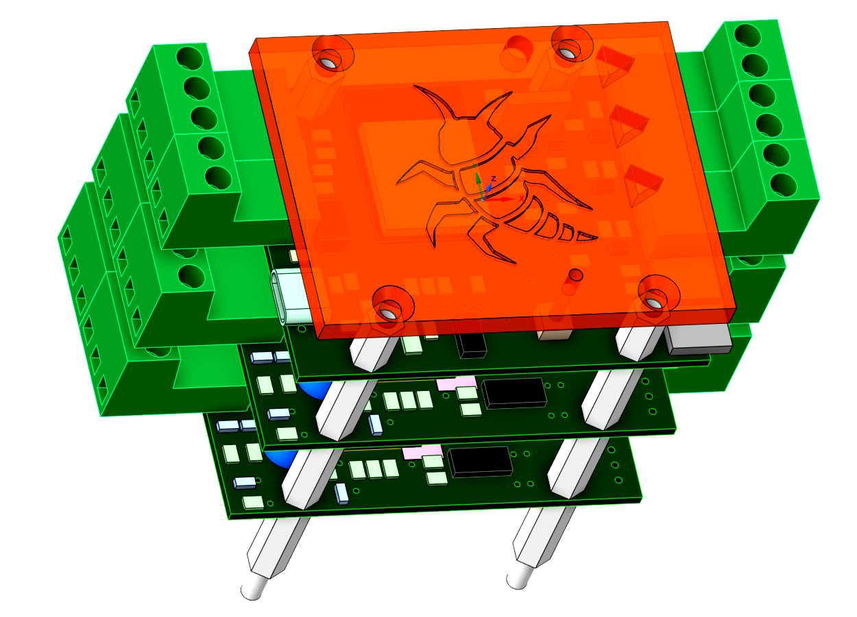
At the core of Bugitrun is the BIR module.
Each BIR includes an integrated test set of inputs and outputs for quick familiarization.
It measures temperatures, switches outputs, drives servos,
and keeps track of the system state.
You monitor everything through a local or cloud dashboard in your browser:
you see live values, can intervene manually, adjust settings,
and write automation logic in a simple BASIC-like language –
while the program itself runs directly inside the BIR.
When that’s not enough, BIR grows with your project.
Its main strength is a 3D spatially oriented bus for connecting external modules – the ecosystem.
These modules are open source, and the community can expand the system
practically without limits with hundreds of variants for different use cases:
relay boards, input blocks, special sensors, and more.
Each module announces itself when connected, gets its own objects and tile color,
and is ready to use instantly.
You don’t rewrite firmware – you just add hardware
and use the new objects directly in your logic.
Multiple BIR modules can cooperate over the network using BIRNET.
A BIR in the boiler room can share data with another in the greenhouse,
or a “server” BIR can collect values from several rooms
and make global decisions.
Technically it’s a simple small HTTP API,
but from the user’s point of view the system behaves like a single distributed whole,
where individual BIRs can see selected values from the others.
Everything is tied together by a simple BASIC-like language running on every BIR.
Your program reads sensor values, sets outputs, calls BIRNET functions,
and keeps running even if you close the dashboard or the internet goes down.
Just a few readable lines are enough to turn a set of sensors and modules
into a system that runs on its own – exactly the way you designed it.
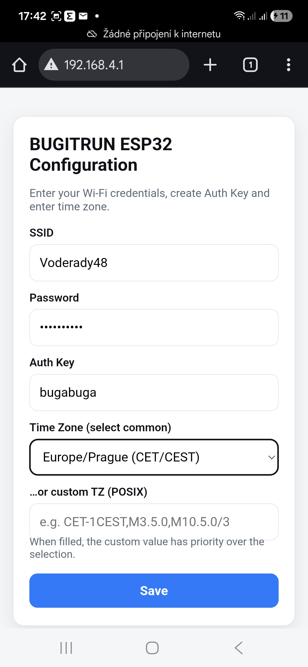
Initialization is used to configure the BIR module’s Wi-Fi connection, Auth Key and time zone. Without a completed initialization, the module does not enter normal operating mode.
If the BIR module starts without stored configuration, it automatically enters initialization mode:
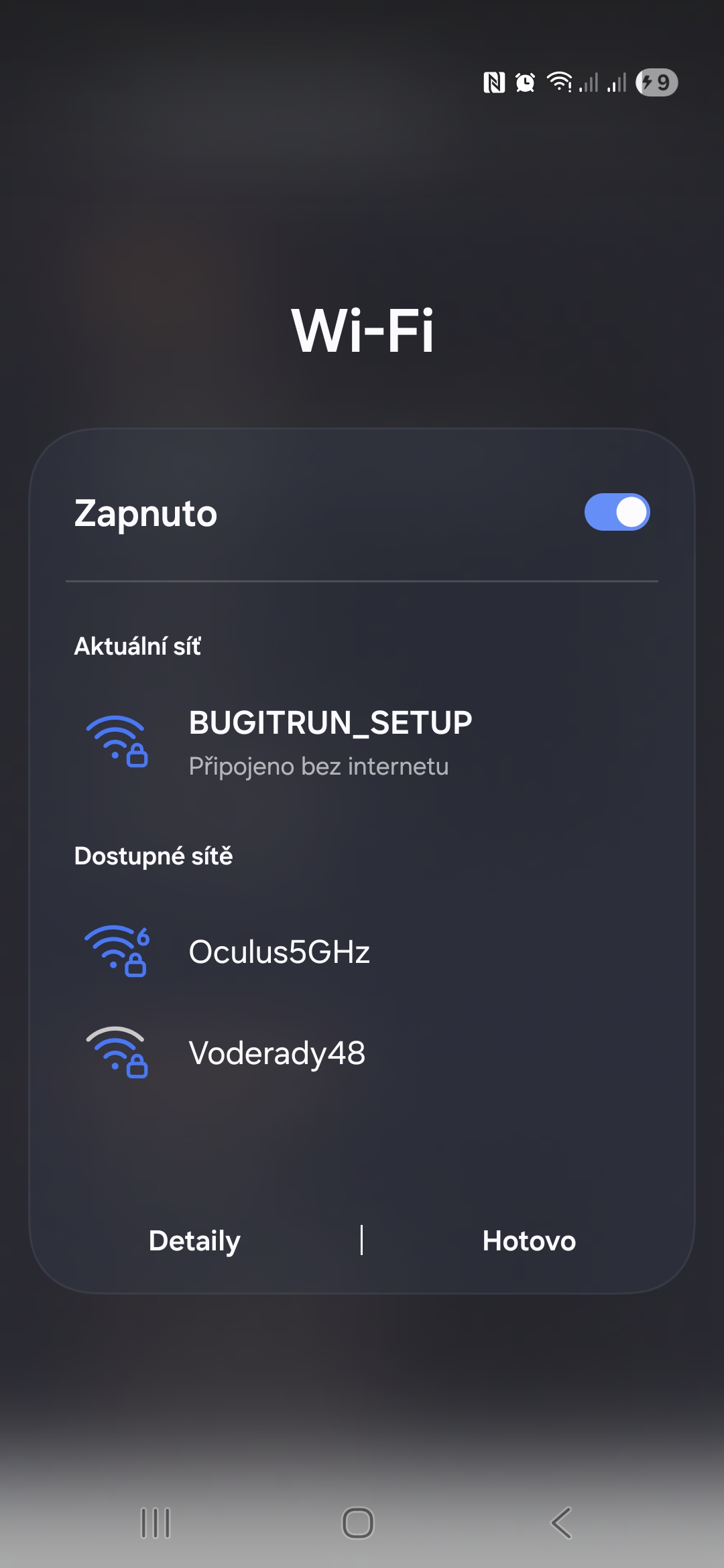
The initialization procedure is as follows:
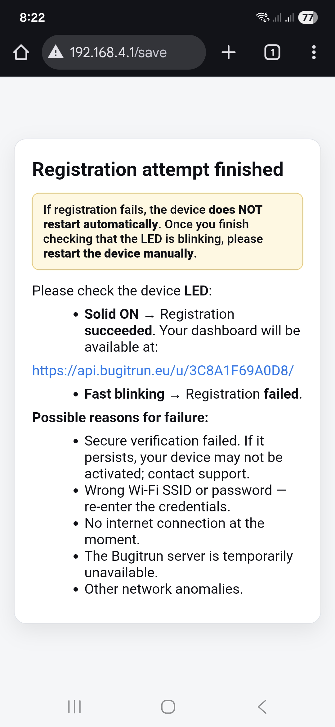
The module stores the provided data, connects to the configured Wi-Fi network and attempts to complete the initialization with the cloud backend.
After the initialization attempt, the result is indicated using the status LED:
If initialization fails (the LED is blinking fast), the BIR module does not restart automatically and must be restarted by briefly disconnecting and reconnecting the power supply. Then try to start the initialization again by holding the button for 10 seconds.
Initialization can be repeated at any time, for example when changing Wi-Fi parameters or the Auth Key, or when handing the module over to a new user. To restart initialization, press and hold the setup button on the BIR module for approximately 10 seconds, until the status LED turns on. The device will erase its stored configuration, reboot, create the BUGITRUN_SETUP Wi-Fi network again and expose the initialization page at http://192.168.4.1, so the initial initialization procedure can be performed once more.
Both the Local and Cloud Dashboards share a common set of core features to ensure a consistent experience.
Both dashboards display sensors and outputs as tiles, each identified by:
System tiles such as TIM, DTE, DAY, OUT, INP, TMP, VAL use predefined colors. For external modules, the dashboard generates a unique tile color based on the module’s three-letter ID.
Internally, each tile corresponds to an object with a three-letter prefix and a numeric index. The core BIR module provides built-in objects OUT_0–OUT_2 (5 V outputs), INP_3 (digital input), SRV_4 and SRV_5 (servo outputs 0–180), followed by optional DS18B20 sensors TMP_6… and channels of external modules such as RLY_x or ADC_x. Numbering is always continuous and any remaining indices are filled with generic VAL_x objects. The total range of tiles is fixed to either 0–44 (no external modules present) or 0–76 (at least one external module detected).
You can rename any object on both dashboards by clicking its name. When choosing a name, it must be unique, must not clash with BASIC keywords, be at most 12 characters long, and may contain only letters, digits, the underscore (_) and the hyphen (-). The user-defined name can then be used directly as an identifier in BASIC code, so you don’t have to reference objects only by their three-letter IDs.
For outputs (e.g. relays), you can click on the value and enter a new float value, which is then sent to the device.
Both dashboards provide a BASIC-like editor where you write your program. Once uploaded, the program runs directly on the BIR module and continues operating even when the device is offline.
Both dashboards allow you to:
This makes it easy to move projects between the Local and Cloud Dashboards or between different BIR modules.
Each dashboard includes an Erase button with two functions:
The Cloud Dashboard runs on the Bugitrun server and is accessed securely over HTTPS using your private access key. It provides a complete remote interface for monitoring and controlling the BIR module from anywhere.
After logging in, you are presented with a live grid of tiles. Each tile represents a single object and updates automatically as new data arrives from the module. Tile colors indicate the object’s module type.
Below the grid is the BASIC editor – a clean editing area for writing and modifying your program. Under the editor, the following project-management controls are available:
Uploaded programs start immediately and continue running even when the device is offline. All Cloud Dashboard projects are stored directly on the server, allowing access from any location.
The upper-right corner menu provides these actions:
Switches to the Local Dashboard hosted directly on the BIR module. This option is available only when your browser is on the same local network as the device.
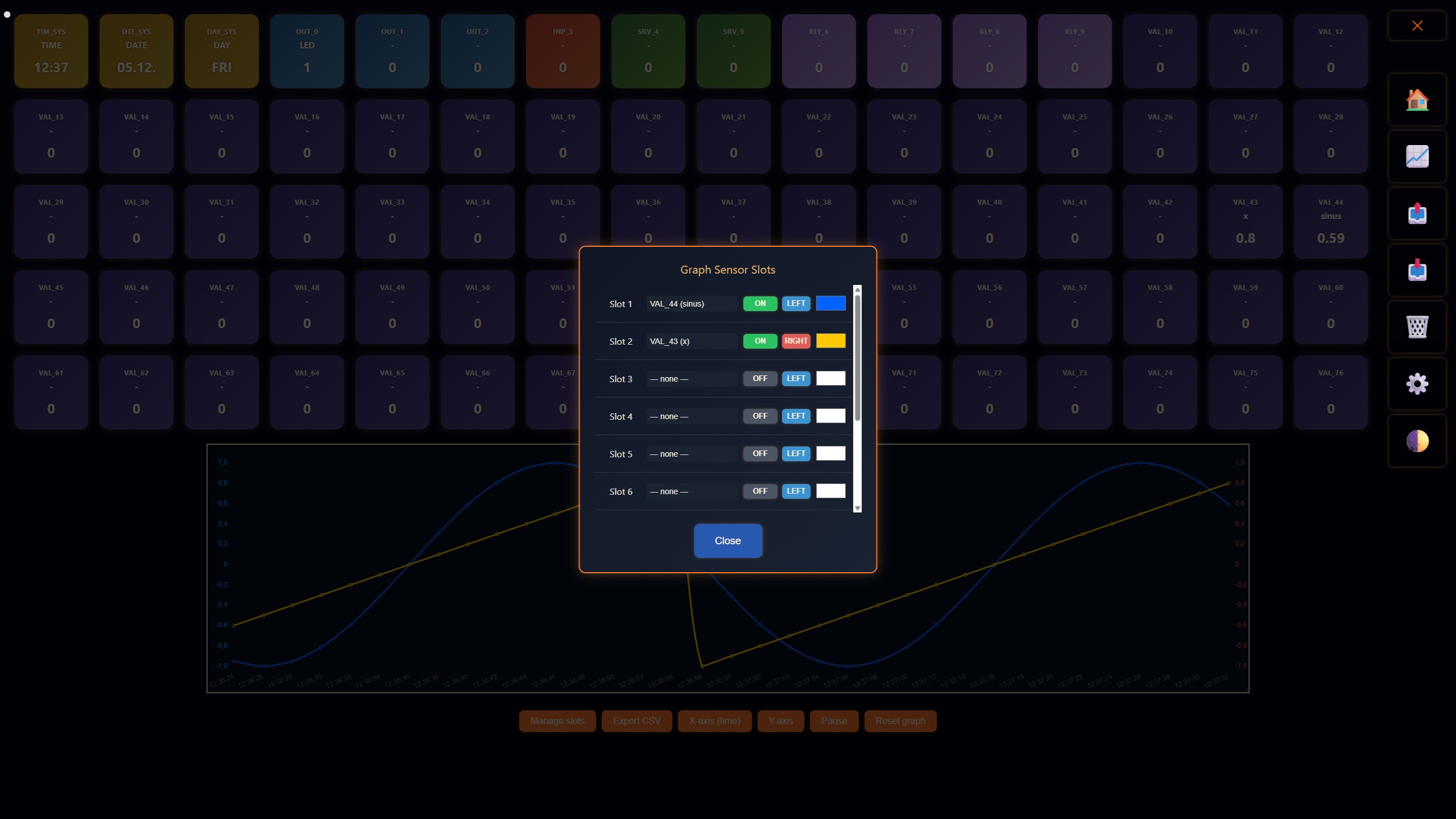
Shows or hides the graph panel. The graph runs entirely inside the browser and stores all data locally in the browser’s memory. Closing or refreshing the page clears the graph. This design provides high performance at scale without any server-side storage.
The graph panel allows you to:
Export and import allow you to share or transfer projects as files directly between devices. You can move a project between multiple BIR modules or between the Cloud and Local Dashboard simply by exporting it to a file and importing it where you need it.
Clears the dashboard state and prepares it for fresh synchronization with the device.
Performs a secure remote firmware update of the BIR module. The update is protected by a cryptographic digital signature (ECDSA). Updates are applied remotely and do not require physical access to the device.
Cycles through the available visual skins. Skins rotate in sequence, and additional designs may be added over time.
The Cloud Dashboard includes a global one-session lock.
This mechanism prevents race conditions and ensures that commands sent from the cloud remain consistent and secure.
The Cloud Dashboard is ideal for remotely supervising and controlling the BIR module – monitoring sensors, managing programs, performing secure firmware updates, sharing projects between devices, or analyzing data over time. In cloud mode, the dashboard shows updated values from the BIR module roughly every 2 seconds, while the Local Dashboard uses a shorter 0.5-second refresh interval for faster, more immediate feedback when you are on the same network.
The Local Dashboard runs directly on the BIR module at its local IP address within your network. For reliable access, you are encouraged to reserve this IP address in your Wi-Fi router. There is no cloud layer involved, which means:
The main area displays a live grid of tiles:
Below the grid, the Local Dashboard provides a BASIC code editor for writing and modifying programs. The editor includes:
In addition, the Local Dashboard supports system-level commands directly inside the BASIC editor:
SYSTEM(COMMAND)SYSTEM() instruction is executed immediately and directly on the BIR module.Command description:
SYSTEM(ENABLE_INSECURE_OTA_ONCE) – enables a one-time emergency OTA update without certificate validation.
Other SYSTEM() commands may be used in the same way.
A small floating menu provides essential local tools:
The Local Dashboard enforces a single active session only within the same browser environment.
Although this is allowed, it is strongly discouraged to run the Local Dashboard on multiple devices or browsers simultaneously, because it can:
For stable operation, the Local Dashboard should be used from a single browser instance at a time. An in-browser overlay prevents parallel sessions within the same browser, but it does not block external devices — therefore the responsibility is on the user to avoid multiple local controllers.
The Local Dashboard is ideal for configuration, testing, development, and emergency maintenance, especially when you need fast, low-latency feedback directly from the device. With its 0.5-second refresh interval (compared to 2 seconds on the Cloud Dashboard), it gives you a much faster visual response when your BASIC program changes values or states. The BASIC program itself always runs directly on the BIR module and is not affected by the dashboard refresh interval. The BASIC interpreter runs offline on the BIR module with a minimum step interval of 10 ms for internal system I/O and 100 ms for external modules.
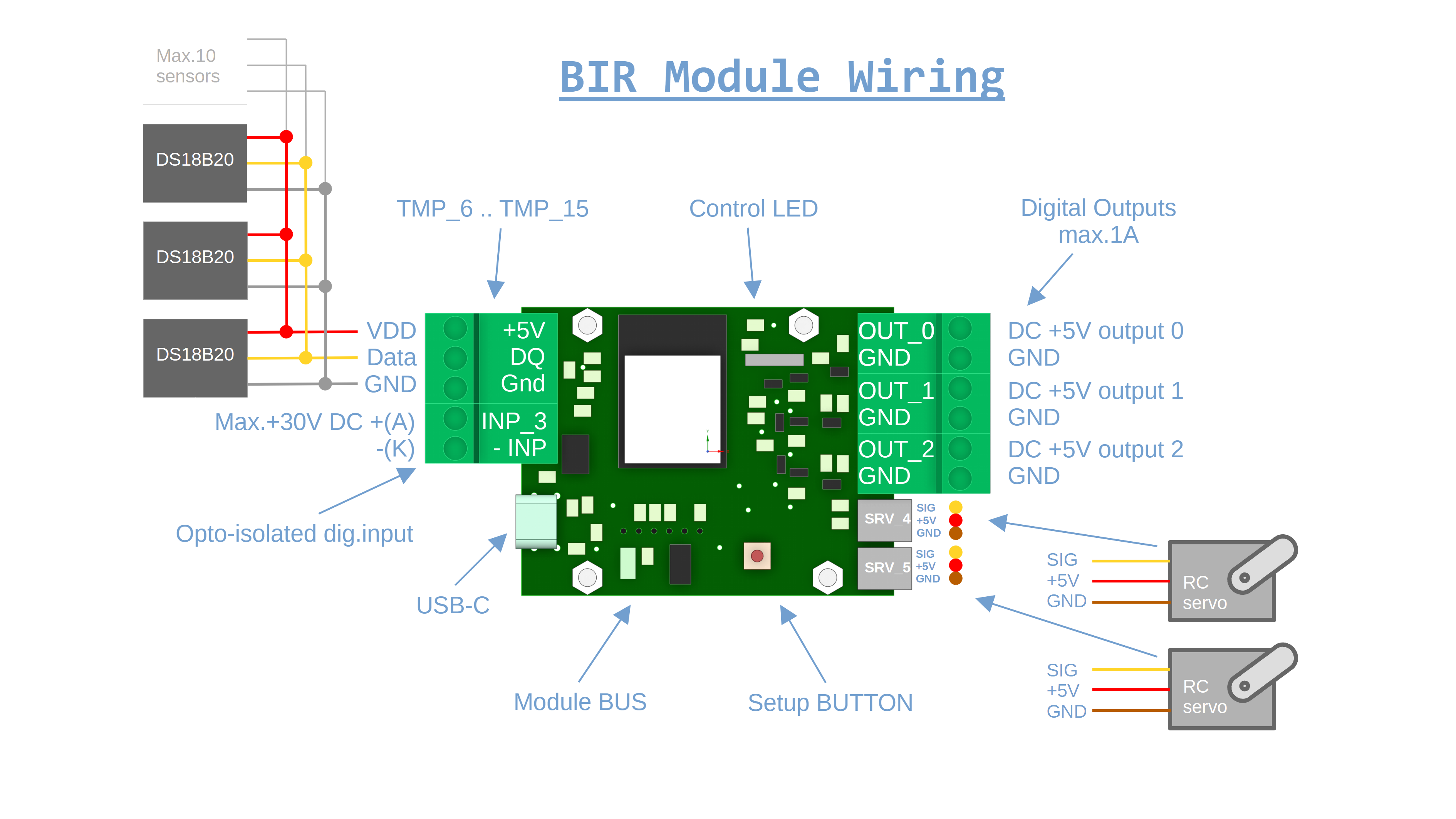
The BIR module is built around an ESP32-WROOM-N4 with a dual-core CPU. It exposes a fixed set of built-in hardware channels that are always present and directly accessible from BASIC. All values are stored internally as floating-point numbers, even if they represent digital states.
The BIR module is powered via a USB-C connector. This connector is used for power only and does not provide a data interface. The 5 V rail is also distributed to the external module bus to supply connected expansion modules. Always choose a USB-C power adapter with respect to the connected external modules and their maximum current consumption.
TMP_6 … TMP_15
(up to 10 sensors in total).TMP_x ID.TMP_x objects are created.TIM_SYS – current time of day (same numeric representation as TIME).DTE_SYS – current date (same numeric representation as DATE).DAY_SYS – current day of week (same numeric representation as DAY).These objects are updated automatically by the BIR firmware and are read-only from BASIC.
All remaining IDs up to the current maximum tile index are exposed as VAL_x objects.
They are pure numeric slots stored in the BIR module and are not tied to any specific hardware.
They are intended as general-purpose variables that survive restarts and can be used in any BASIC program.
If no external modules are connected, the dashboards show tiles from index 0 up to 44
(OUT / INP / SRV / TMP and then a block of VAL_x objects).
If at least one external module is detected, the available tile range is extended to 0–76.
The free space between the last hardware ID and the maximum index is always filled with VAL_x.
The built-in BIR hardware (OUT / INP / SRV / TMP / VAL) is primarily meant for learning, prototyping and smaller projects. Because these channels are connected directly to ESP32 pins, the internal response is very fast and latency is minimal.
BIRNET allows multiple BIR modules to communicate with each other directly over the local network, without using the cloud backend. Typical use cases include sharing sensor values between rooms, synchronizing outputs across devices, or offloading part of the logic to a dedicated “server” BIR.
BIRNET is implemented as a small HTTP-based API between BIR modules. Each BIR exposes simple LAN endpoints and the BASIC interpreter provides high-level commands that hide the HTTP details and handle timeouts internally.
The simplest form of BIRNET is reading a single value from another BIR using the GET() function.
It is used directly inside BASIC expressions:
0  WAITINIT
10 LET LED = GET("192.168.0.200","OUT_0", 500)
20 LET VAL_44 = BIRNETSTAT
30 GOTO 10
Parameters:
OUT_0, TMP_1, VAL_10),
If the timeout is omitted, it defaults to 1000 ms. The timeout is internally clamped
to the range 300–5000 ms. Even if the server responds faster, the GET() command
blocks the BASIC interpreter for the full timeout duration – this guarantees that there is no internal queue
of pending TCP requests and prevents network overload when the remote module is offline or restarting.
On the server side, the request is handled by a lightweight /peer endpoint. If the target BIR
is not yet initialized (for example, still waiting for sensors to come online), it returns a temporary
NOT_READY state and the client simply finishes the GET() without updating any value.
BIRNET SINGLE demo:
OUT_0 on the server module.OUT_0 from the server and mirrors the LED.
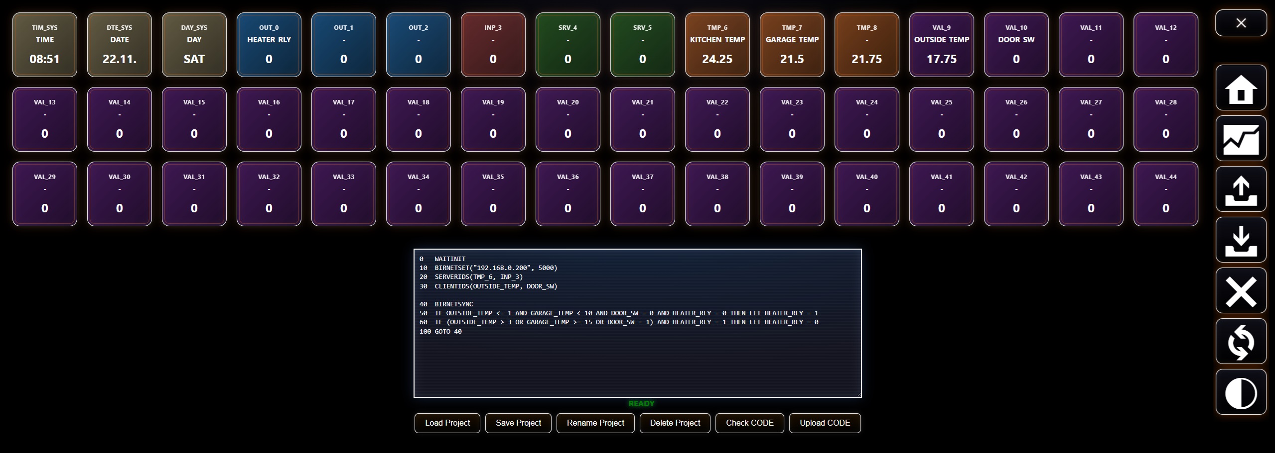
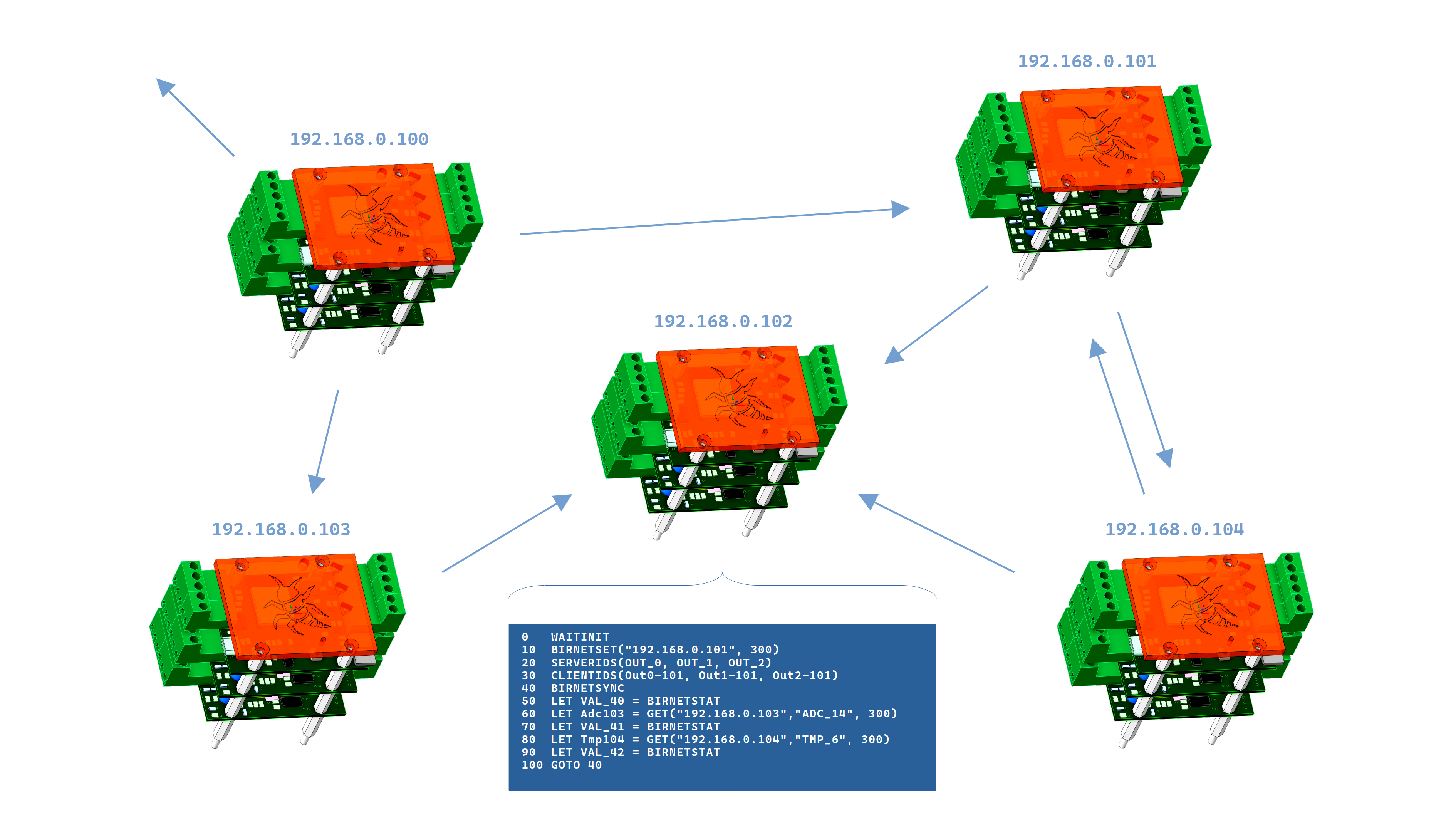
For more advanced scenarios, BIRNET provides a multi-value synchronization mechanism. Instead of calling
GET() multiple times, the client can fetch several values from the server in one step and
update multiple local objects atomically.
The sequence is always:
Configures the target BIR and timeout for all subsequent BIRNETSYNC calls:
BIRNETSET("192.168.0.200", 300)Defines which remote IDs will be read from the server. Up to 10 IDs are supported:
SERVERIDS(OUT_0, OUT_1, OUT_2)Defines which local IDs will be overwritten by the values from the server. The number and order of local IDs must match the remote IDs:
CLIENTIDS(OUT_0, OUT_1, OUT_2)After this configuration, the first remote ID maps to the first local ID, the second to the second, etc.
Executes one synchronization step:
0 WAITINIT
10 BIRNETSET("192.168.0.200", 300)
20 SERVERIDS(OUT_0, OUT_1, OUT_2)
30 CLIENTIDS(OUT_0, OUT_1, OUT_2)
40 BIRNETSYNC
50 LET VAL_44 = BIRNETSTAT
60 GOTO 40
Internally, the client sends a single request to the server (endpoint /peer_multi)
and receives all requested values at once. The most important property is
all-or-nothing behavior:
CLIENTIDS are updated in one step.This makes multi-sync safe for professional automation scenarios where partial updates could cause inconsistent states or unwanted behavior.
BIRNET MULTI demo:
BIRNETSTAT is a read-only numeric value that always contains the result of the last
BIRNET operation (GET(...) or BIRNETSYNC). It can be used anywhere a number
is expected (for example in LET or IF).
The value is set automatically to one of the following codes:
  0   - no BIRNET request has finished yet (initial state after boot or reset)
200   - last BIRNET request succeeded and the remote module returned valid data
 -1   - connection error (remote BIR could not be reached – Wi-Fi not connected or HTTP connection failed)
 -2   - remote BIR responded, but the response was empty or invalid
400   - invalid request (wrong or missing ID in the command)
404   - requested ID does not exist on the remote BIR
503   - remote BIR is not ready yet (for example its sensors or external modules are still initializing)
GET() and BIRNETSYNC are blocking operations: they pause the BASIC interpreter
for the configured timeout on each call.SERVERIDS – an unknown ID on the server side causes the entire sync
to be skipped, by design, to keep your client state consistent.The Ecosystem represents a set of highly compatible expansion modules for sensors, inputs, outputs, and basically any “object” you can imagine around an MCU-based system. Each external module does not deal with any user interaction — it is purely hardware that serves a specific sensor or function and exposes its values/channels to the BIR module.
Every module has its own 3-letter ID made of uppercase letters, for example RLY.
This ID also determines the tile color generated on the dashboards according to the internal color logic.
In the module firmware, you typically define the module ID, number of channels, and the module type
(input / output). Each external module provides a defined number of channels of the same type.
The channel count is determined by the module’s hardware and firmware, with a maximum of 8 channels per module.
Up to 8 external modules can be connected to the expansion bus, resulting in up to 64 objects available to a single BIR module.
DS18B20 sensors are not counted as external modules. Up to 10 DS18B20 sensors can be connected directly to the BIR module. These sensors are not plug-and-play: if one stops communicating, the BIR module will only show an error on the corresponding tile, and whenever DS18B20 sensors are added or removed, the BIR module must be restarted. This does not apply to external modules, which are plug-and-play. They can be connected and disconnected while the system is running, and the BIR module will automatically detect the change and add or remove the modules internally and in the dashboards.
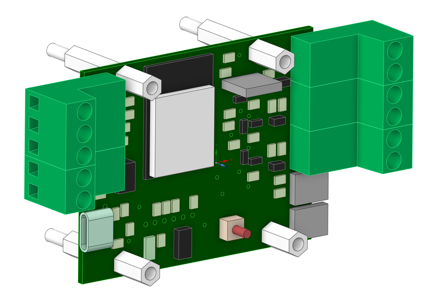
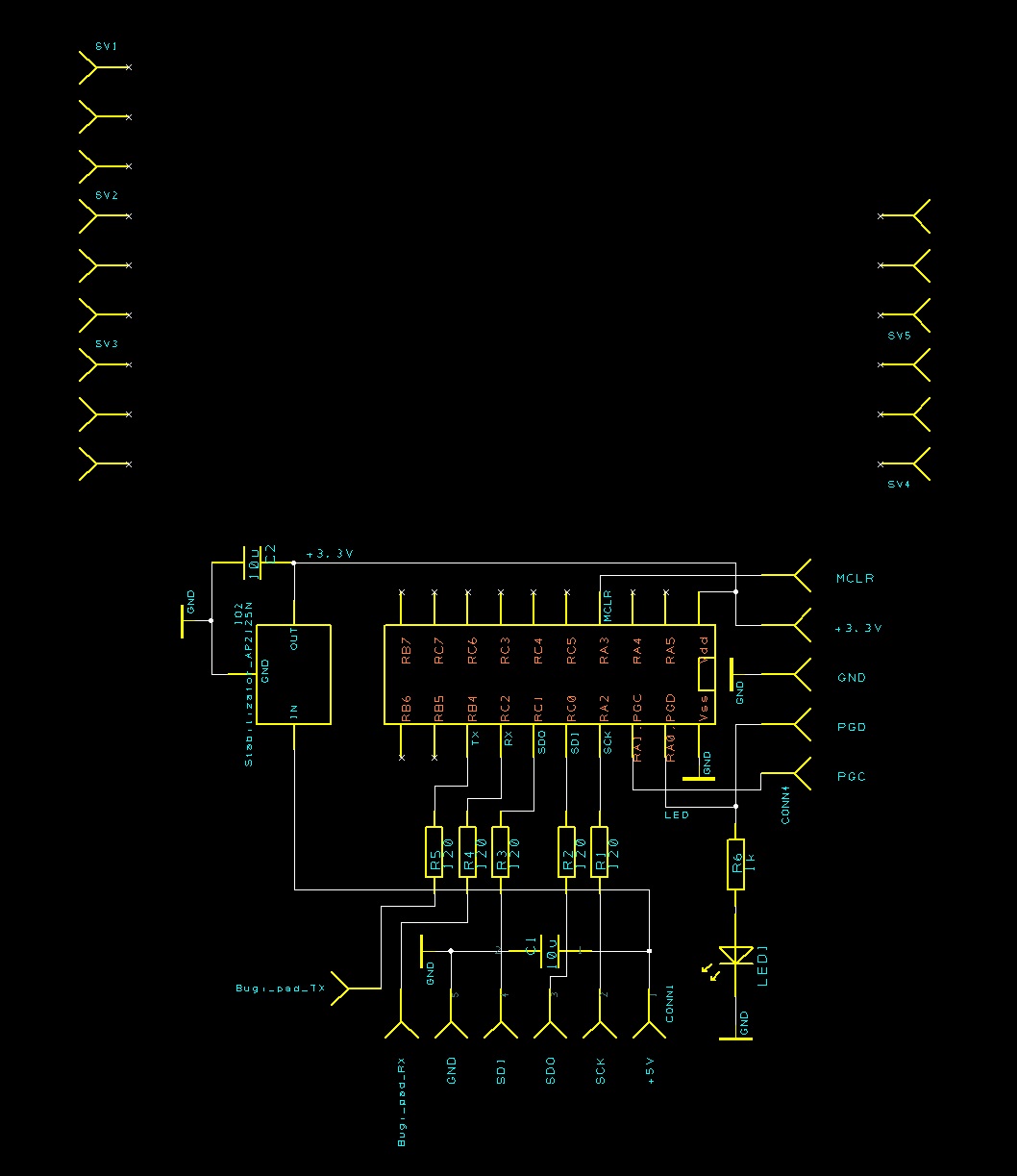
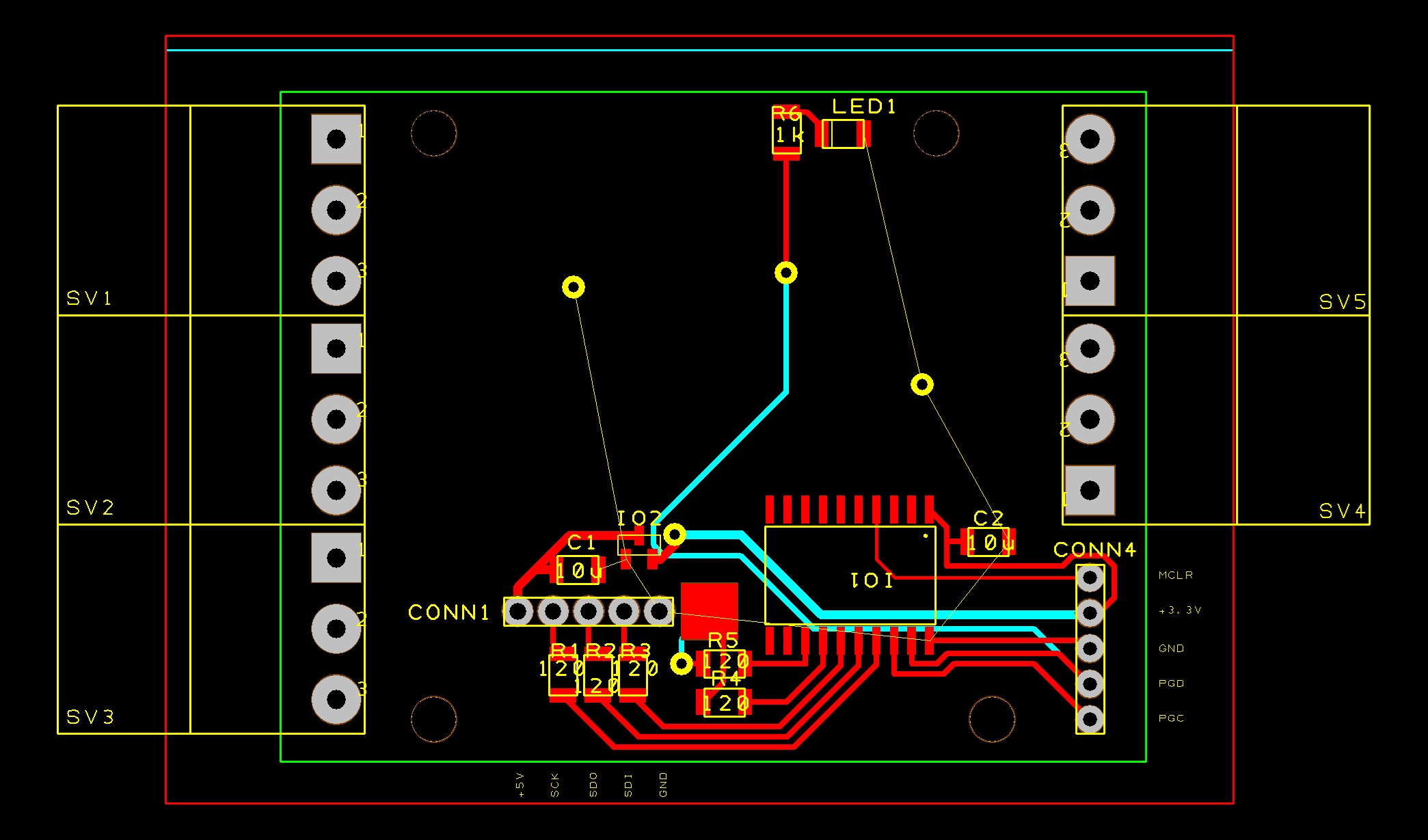
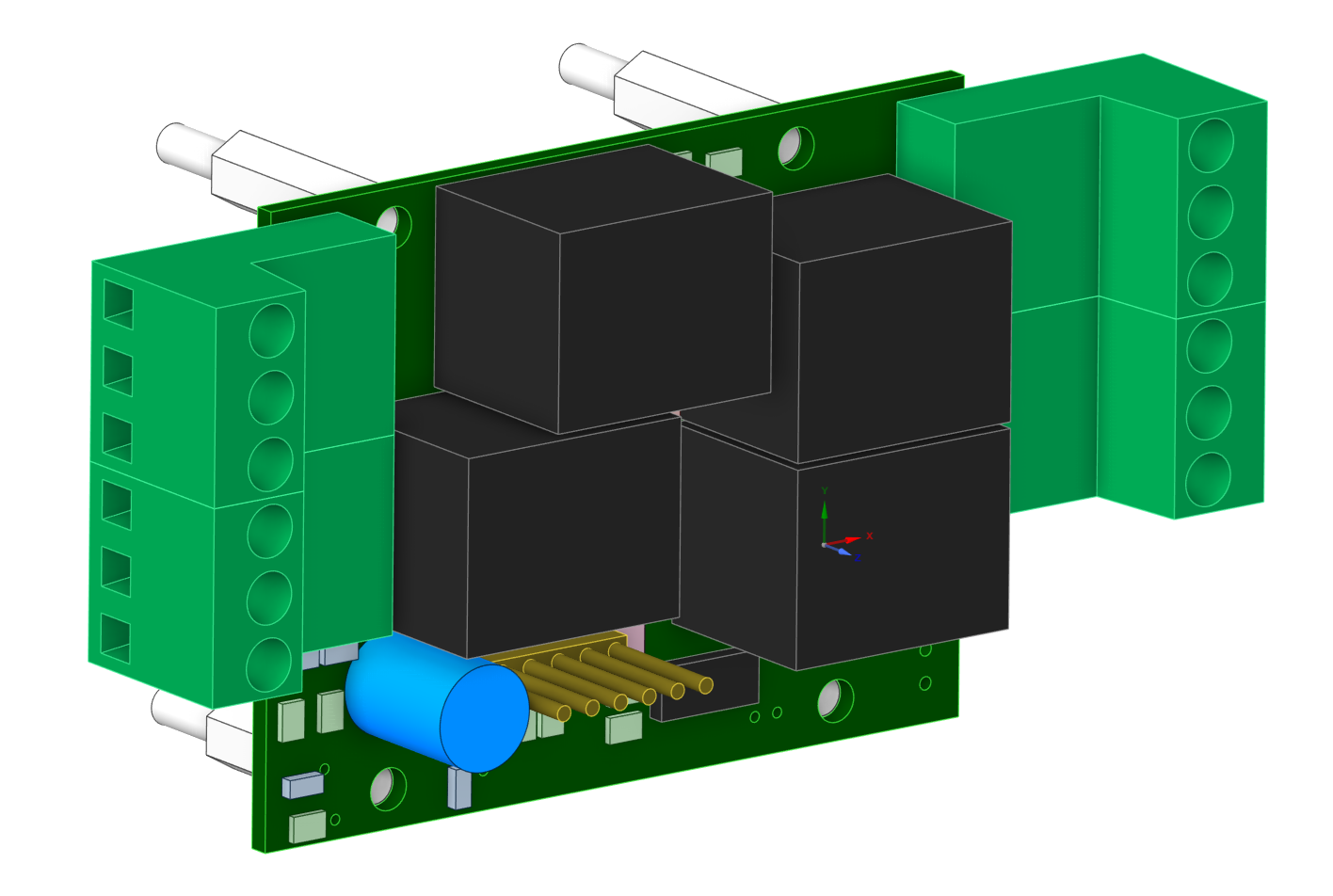
The Ecosystem is open source — anyone can design and build their own modules. This manual section describes the default reference wiring, including a reference PCB design and a basic firmware template using the Microchip PIC18F15Q40 as the module MCU.
The reference schematic and PCB were created in DesignSpark PCB 12.0. The reference firmware is built in MPLAB X using the XC8 compiler v3.00 (pack 1.27.449).
However, you can use any MCU as long as it supports UART and SPI communication.
The LET instruction assigns the result of a numeric expression to a target NAME.
All values in BIR BASIC are stored as floating-point numbers.
LET NAME = numeric_expressionOUT_0, OUT_1, OUT_2, INP_3, SRV_4, SRV_5, TMP_6, module IDs such as RLY_7, ADC_11, or generic value objects VAL_x up to the current hardware limit), orheater, room_temp).AVG_1, DEL_123, MIX_42.
IF, THEN, TIME, DATE, DAY, ABS, RND, PI, BIRNETSTAT, …).AND, OR, NOT) are not allowed inside numeric expressions.
They are reserved for boolean expressions in IF conditions.TMP_6, OUT_0, VAL_20, TIM_SYS) or their user-defined names (e.g. heater, room_temp),AAA_123 pattern (e.g. AVG_1, MIX_1, DEL_10),+, -, *, /,+ and -,( ... ),ABS, MAX, MIN, SIN, COS, TAN, RND, LOG, LN, EXP, ROUND, FLOOR, CEIL, SQRT, …,PI, E, BIRNETSTAT.LET cannot contain an IF expression – conditions belong in a separate
IF ... THEN ... line.GET() can be used in LET only as the whole right-hand side, e.g.
LET X = GET(...).
It cannot be combined inside another expression like 1 + GET(...).Simple assignment using system IDs:
10 LET OUT_0  = 1              # turn relay ON
20 LET VAL_20 = TMP_6          # copy current temperature into VAL_20
Assignment using user-defined names:
10 LET heater    = 1           # 'heater' is a user name mapped to OUT_0
20 LET room_temp = TMP_6       # mix of user name and system ID
30 LET LED       = 1 - LED     # toggle LED (LED is an existing object name)
Using hidden standalone variables (AAA_123 pattern):
10 LET AVG_1 = (TMP_6 + TMP_7) / 2    # hidden variable AVG_1
20 LET DEL_1 = ABS(AVG_1 - 21)        # reuse AVG_1 in another expression
30 LET MIX_1 = SIN(PI / 2) * 10       # another hidden variable
Using built-in functions and parentheses in a more complex expression:
10 LET MIX_1 = ( MAX(TMP_6, TMP_7) + ABS(VAL_20 - 3.5) ) / 2
20 LET CMD_1 = ROUND( MIX_1 / 5 )
30 LET GRF_1 = RND(50) + LOG( TMP_6 + 10 )
Using GET() inside LET (only as the whole expression):
10 LET heater = GET("192.168.0.200","OUT_0", 500)
20 LET STA_1  = BIRNETSTAT          # store last BIRNET status code into a hidden variable
The IF instruction evaluates a boolean expression and, depending on the result, executes
one of two possible actions:
IF boolean_expression THEN single_command
IF boolean_expression THEN single_command ELSE single_command
After THEN and ELSE you can use:
LET ...DELAY ...GOTO ...GOSUB ...RETURNPRINT ...IF ... THEN ... without its own ELSE.
Other BASIC commands (such as WAITINIT, WAITCLOUDTICK, BIRNETSET, SERVERIDS, CLIENTIDS, BIRNETSYNC, FOR, NEXT, …) must be placed on their own line – they cannot be used directly after THEN or ELSE.
Boolean expressions in IF support:
LET),Comparison operators:
==
=
!=
<
>
<=
>=
Each side of the comparison is a numeric expression, for example:
TMP_6 > 21(TMP_6 + TMP_7) / 2 <= 25ABS(room_temp - 21) < 0.5BIRNETSTAT = 200Logical operators:
ANDORNOT
Operators AND, OR and NOT are written as words (not && or ||)
and are case-insensitive (and, Or, NOT all work).
Precedence:
NOT has the highest priority,AND,OR.
Parentheses ( ... ) can be used to override the default precedence.
Truth value without an explicit comparison:
If no comparison operator is found (for example IF heater THEN ...),
the numeric expression is evaluated and treated as:
THEN is executed.ELSE part is present, the command after ELSE is executed.ELSE, the line does nothing.
Only one command is allowed in each branch – there is no support for multiple commands separated by : or similar.
If you need multiple actions, use GOTO or GOSUB to jump to a block of code on separate lines.
Simple threshold:
10 IF room_temp < 21 THEN LET heater = 1
20 IF room_temp > 23 THEN LET heater = 0
Range check with ELSE:
10 IF TMP_6 >= 18 AND TMP_6 <= 24 THEN LET comfort = 1 ELSE LET comfort = 0
Boolean-style numeric expression:
10 IF heater THEN LET LED = 1 ELSE LET LED = 0 # 'heater' is true when its value != 0
Nested IF (safe form):
10 IF TMP_6 > 25 THEN IF window = 0 THEN LET heater = 0
In this form, the inner IF is the single command after THEN.
The inner IF should not use its own ELSE on the same line – any ELSE always belongs
to the first IF on the line. For more complex conditions, use logical operators
(AND, OR, NOT) or split the logic into multiple lines.
Example program (IF THEN ELSE DEMO):
# =================
# IF THEN ELSE DEMO
# =================

10 LET SWITCH = 1
20 IF (VALUE = 32 OR VALUE = 64 OR VALUE = 128) AND SWITCH = 1 THEN LET LED1 = 1 ELSE LET LED1 = 0
30 IF (VALUE = 10 OR VALUE = 20 OR VALUE = 30) AND SWITCH = 1 THEN LET LED2 = 1 ELSE LET LED2 = 0
40 IF (VALUE = 11 OR VALUE = 22 OR VALUE = 33) AND SWITCH = 1 THEN LET LED3 = 1 ELSE LET LED3 = 0
50 DELAY 100
60 GOTO 20
The GOTO instruction jumps to another line in the program.
The target is specified by its line number – the number at the beginning of a BASIC line.
GOTO lineNumber10, 100, 250).GOTO targets point to existing lines before the program is uploaded.
If a GOTO to a non-existing line somehow reaches the interpreter, it is ignored at runtime and execution continues with the next line.GOTO can be used:
20 GOTO 100),THEN or ELSE in an IF line (e.g. 10 IF VALUE > 0 THEN GOTO 100).: or similar.# ===============
# IF AS CASE DEMO
# ===============
# Replace select case statement
0 LET SPEED = 100
10 LET VALUE = RND()
20 DELAY SPEED
30 IF VALUE >= 0.0 AND VALUE < 0.2 THEN GOTO 1000
40 IF VALUE >= 0.2 AND VALUE < 0.4 THEN GOTO 2000
50 IF VALUE >= 0.4 AND VALUE < 0.6 THEN GOTO 3000
60 GOTO 10
1000 LET LED1 = 1 - LED1
1010 GOTO 10
2000 LET LED2 = 1 - LED2
2010 GOTO 10
3000 LET LED3 = 1 - LED3
3010 GOTO 10
GOSUB is used to call a subroutine located at another line number.
The interpreter remembers where it came from, jumps to the subroutine, and later
RETURN brings execution back to the line after the last GOSUB.
GOSUB lineNumber
RETURNGOSUB targets before upload and reports
calls to missing lines as errors.GOSUB is executed:
GOSUB calls).GOSUB calls no longer enter the subroutine
(the call is effectively ignored and execution stays in the main flow).GOSUB can also be used after THEN or ELSE in an IF line.RETURN should be placed at the end of a subroutine.RETURN is executed:
GOSUB is taken from the stack,GOSUB.RETURN is executed when no GOSUB is active, it has no effect and
execution simply continues with the next line.RETURN, it continues
into the following lines. For clarity, it is recommended to always end subroutines with an explicit
RETURN.10 GOSUB 100
20 DELAY 1000
30 GOTO 10
100 LET LED = 1
110 DELAY 200
120 LET LED = 0
130 RETURN
10 IF TMP_6 > 25 THEN GOSUB 100
20 GOTO 10

100 LET heater = 1
110 RETURN
In the second example, the subroutine at line 100 is called only when
the condition in line 10 is true. After RETURN, execution continues at line 20.
# =========
# GOSUB DEMO
# =========

10 LET LED1 = 1                    # LEVEL 0
20 GOSUB 100
30 DELAY 500
40 LET LED1 = 0
50 DELAY 500
60 GOTO 10

100 IF LEVEL == 0 THEN RETURN      # LEVEL 1
110 LET LED2 = 1
120 IF LEVEL == 2 THEN GOSUB 200
130 DELAY 500
140 LET LED2 = 0
150 DELAY 500
160 GOTO 100

200 LET LED3 = 1                   # LEVEL 2
210 DELAY 500
220 LET LED3 = 0
230 DELAY 500
240 IF LEVEL == 1 THEN RETURN
250 GOTO 200
The FOR loop repeats a block of code a given number of times.
The loop variable is numeric and is updated automatically on each NEXT.
FOR var = start TO end
FOR var = start TO end STEP step_value
...
NEXT
NEXT varVAL_10, OUT_0, TMP_6),LOOP, SPEED, INC1),AAA_123 pattern (e.g. LOP_1).STEP 1 is used by default,STEP is allowed (counting down),STEP is not recommended, because it makes the loop effectively run only once.FOR must have a matching NEXT.
Nested loops are supported and must be properly paired in the source code.NEXT can optionally specify the loop variable
(e.g. NEXT LOOP). If present, the name must match the corresponding FOR.
If omitted, the nearest active FOR is used.LET, IF, DELAY, GOSUB, PRINT, etc.).Simple loop 0–9:
10 FOR LOOP = 0 TO 9
20   LET OUT_0 = 1
30   DELAY 200
40   LET OUT_0 = 0
50   DELAY 200
60 NEXT LOOP
Loop with STEP and a helper variable:
10 FOR LOOP = 0 TO 20 STEP 0.5
20   LET INVERSE = 20 - LOOP
30   LET LED = 1
40   DELAY LOOP
50   LET LED = 0
60   DELAY INVERSE
70 NEXT LOOP
# ==================
# FOR NEXT STEP DEMO
# ==================

0   LET CYCLES = 0
1   LET FAST_STEP = 5

10  FOR INC1 = 2.5 TO -2.5 STEP -0.1
20    FOR INC2 = 0 TO 200 STEP FAST_STEP
30      LET LED1 = 1
40      DELAY 50
50      LET LED1 = 0
60      DELAY 50
70    NEXT INC2
80    LET FLAG = FLAG + 1.5
90    DELAY 1000
100 NEXT INC1

110 LET LED1 = 1
120 LET FLAG = 0
130 DELAY 10000
140 LET CYCLES = CYCLES + 1
150 GOTO 10
The DELAY instruction pauses program execution for a specified number of milliseconds.
DELAY ms_expressionDELAY uses a time anchor to keep the loop period stable:
successive DELAY calls with the same value create a regular timing pattern
(useful in main loops).WAITCLOUDTICK, the next DELAY automatically re-synchronizes
its internal time anchor to the current moment, so timing continues smoothly from the cloud tick.DELAY the BASIC interpreter task is paused and does not execute other BASIC lines,
but the BIR firmware and other internal tasks continue running normally.10 LET MS = 200
20 LET LED = 1
30 DELAY MS
40 LET LED = 0
50 DELAY MS
60 GOTO 20
The WAITINIT instruction waits until the module finishes initialization
and all connected sensors (DS18B20 and external modules) have their first valid readings.
WAITINITWAITINIT takes no arguments.0), but it can be used on any line.
If initialization is already finished, WAITINIT returns immediately.WAITINIT line and sleeps for short intervals, so the rest of the program does not run yet.WAITINIT, the BASIC program starts immediately after boot and may use
initial sensor values that are still zero or otherwise invalid.WAITINIT must be used as a standalone command on its own line.
It cannot be placed after THEN or ELSE in an IF statement.# =============
# WAITINIT demo
# =============
# For this demo, at least one DS18B20 sensor is required.
# The WAITINIT command waits for the initialization to complete
# and for the first valid readings from all DS18B20 and external sensors.
0 WAITINIT
1 LET FIRST_TEMP = TEMP
10 LET LED = 1 - LED
20 DELAY 500
30 GOTO 10
The WAITCLOUDTICK instruction blocks the BASIC program until the cloud server
signals a new synchronization tick (when the online dashboard is active).
WAITCLOUDTICKWAITCLOUDTICK takes no arguments.WAITCLOUDTICK until the next cloud tick arrives.
The BASIC interpreter repeatedly sleeps in short intervals while it is waiting.WAITCLOUDTICK unblocks, the internal timing anchor
for DELAY is re-synchronized, and execution continues on the next line.WAITCLOUDTICK line until a client reconnects.WAITCLOUDTICK must be used as a standalone command on its own line.
It cannot be placed after THEN or ELSE in an IF statement.# ====================
# WAIT CLOUD TICK demo
# ====================
# Blinks the LED for 0.5 s, then waits for the next cloud tick.
# WAITCLOUDTICK blocks until the server cycle signals a new tick.
# Each tick increments CLOUD-TICKS to track successful cloud syncs.
# If the online dashboard is closed, the BIR module detects the client is offline
# and parks the BASIC program on line 40 (WAITCLOUDTICK).
10 LET LED = 1
20 DELAY 500
30 LET LED = 0
40 WAITCLOUDTICK
50 LET CLOUD-TICKS = CLOUD-TICKS + 1
60 GOTO 10
The PRINT instruction attaches a short text label (a "mask") to a numeric value
for display on the dashboard. The underlying variable always keeps its real floating-point value.
PRINT "text", IDVAL_10, TMP_6, OUT_0, Door if it is the real ID, …).""), the text mask is removed and only the numeric value is shown again.PRINT can also be used after THEN or ELSE in an IF line
as a single command.# ==========
# PRINT demo
# ==========
# This demo shows how PRINT adds a text "mask" to a numeric value.
# If the first parameter is a non-empty string (up to 10 characters), that text is displayed instead of the raw value.
# If the first parameter is an empty string (""), the text is removed and only the numeric value is shown.
# The variable itself always keeps its real floating-point value for all calculations and conditions.
10 LET Door = 1 - Door
20 IF Door = 1 THEN PRINT "Open", Door ELSE PRINT "Closed", Door
30 LET DoorValue = Door
40 LET INC = INC + 1
50 IF INC >= 5 THEN GOSUB 100
60 WAITCLOUDTICK
70 GOTO 10
# Reset string mask back to the raw numeric value
100 PRINT "", Door
110 LET INC = 0
120 RETURN
BIR BASIC provides three read-only system parameters for working with time and calendar:
TIME, DATE and DAY.
They can be used in expressions and IF conditions just like numeric values.
17.5, 6:15 as 6.25.day + month/100.
9.01, 31 December is 31.12.SUN=0, MON=1, TUE=2, WED=3, THU=4, FRI=5, SAT=6.
TIME, DATE and DAY are read-only system parameters.
They cannot be used on the left side of LET or as loop variables in FOR.TIME, DATE or DAY on the dashboard.
In IF conditions, special readable forms are supported and automatically converted
to numeric expressions by the dashboard check:
TIME >= 12:02 AND TIME < 12:03 → comparison with a time range,DATE = 9.1 → comparison with the numeric date value,DAY = FRI → comparison with the numeric day-of-week code.Note about TIME comparisons:
TIME changes every second and is stored as a floating-point value.TIME = 17:31 is not recommended,
because the internal value and the rounded literal almost never match exactly.IF TIME >= 17:31 AND TIME < 17:32 THEN ...# =============
# DATETIME demo
# =============
10 IF TIME >= 12:02 AND TIME < 12:03 THEN LET LED1 = 1 ELSE LET LED1 = 0
20 IF DATE = 9.1 THEN LET LED2 = 1 ELSE LET LED2 = 0
30 IF DAY = FRI THEN LET LED3 = 1 ELSE LET LED3 = 0
40 DELAY 1000
50 GOTO 10
BIR BASIC supports a set of built-in math functions and constants that can be used
in any numeric expression (in LET, IF, FOR, etc.).
All function names and constants are case-insensitive.
Functions:
ABS(x) – absolute valueMIN(a, b), MAX(a, b) – minimum / maximum of two valuesMOD(a, b) – remainder after division (floating-point modulus)SIGN(x) – returns -1 for negative, 0 for zero, 1 for positive valuesROUND(x), FLOOR(x), CEIL(x) – rounding, floor and ceilingSQRT(x) – square rootLOG(x) – base-10 logarithmLN(x) – natural logarithm (base E)EXP(x) – exSIN(x), COS(x), TAN(x) – trigonometric functions, x is in radiansRND() – random value in the range 0..1RND(max) – random value in the range 0..maxConstants:
PI – π (≈ 3.14159)E – Euler's number (≈ 2.71828)BIRNETSTAT – last BIRNET status code (numeric value that can be used in expressions and IF conditions).# =========
# Math DEMO
# =========
# -----------------------------------------
# BLOCK A: Basic arithmetic (std precedence)
# -----------------------------------------
1000 LET VAL_14 = 2 + 3 * 4 # 14
1010 LET VAL_15 = 10 / 2 * 3 # 15
1020 LET VAL_16 = 5 - 2 * 3 + 4 * 2 # 7
1030 LET VAL_17 = -5 + 2 * 3 # 1
1040 LET VAL_18 = --5 + -+-+3 # 8
# -----------------------------------------
# BLOCK B: Parentheses (explicit priority)
# -----------------------------------------
1100 LET VAL_19 = (5 + 3) * 2 # 16
1110 LET VAL_20 = (10 - 4) / (2 + 1) # 2
1120 LET VAL_21 = (3 + (2 * (1 + 1)))# 7
# -----------------------------------------
# BLOCK C: Math functions & constants
# -----------------------------------------
1200 LET VAL_22 = ABS(-5) # 5
1210 LET VAL_23 = SQRT(81) # 9
1220 LET VAL_24 = MIN(2, 8) # 2
1230 LET VAL_25 = MAX(2, 8) # 8
1240 LET VAL_26 = MOD(17, 5) # 2
1250 LET VAL_27 = ROUND(3.6) # 4
1260 LET VAL_28 = FLOOR(3.8) # 3
1270 LET VAL_29 = CEIL(3.2) # 4
1280 LET VAL_30 = SIGN(-42) # -1
1290 LET VAL_31 = LOG(100) # 2
1300 LET VAL_32 = LN(2.71828) # 1(≈)
1310 LET VAL_33 = EXP(2) # 7.389(≈)
1320 LET VAL_34 = SIN(PI / 2) # 1
1330 LET VAL_35 = COS(PI) # -1
1340 LET VAL_36 = TAN(PI / 4) # 1
1350 LET VAL_37 = RND() # 0..1
1360 LET VAL_38 = RND(100) # 0..100
1370 LET VAL_39 = E # 2.71828...
# -----------------------------------------
# BLOCK D: Variables combined with expressions
# -----------------------------------------
1400 LET OUT_0 = 1
1410 LET VAL_40 = 5 * OUT_0 + VAL_22 / 2 # 7.5
1420 LET VAL_41 = (VAL_40 + SQRT(VAL_23)) / 2 # 5.25
# -----------------------------------------
# BLOCK E: IF / THEN / ELSE with math
# -----------------------------------------
1500 LET VAL_41 = (VAL_40 + SQRT(VAL_23)) / 2 # z předchozího bloku
1510 IF VAL_41 > 10 THEN LET OUT_0 = 1 ELSE LET OUT_0 = 0
1520 IF ABS(SIN(PI/2) - 1) < 0.001 THEN LET OUT_1 = 1
1530 IF RND() > 0.5 THEN LET OUT_2 = 1 ELSE LET OUT_2 = 0
# -----------------------------------------
# BLOCK F: Loops and DELAY with expressions
# -----------------------------------------
1600 LET VAL_43 = 1000
1610 FOR VAL_44 = 1 TO 5 STEP 1
1620 LET OUT_1 = 1
1630 DELAY 1000 + VAL_43 / 2 # 1500 ms
1640 LET OUT_1 = 0
1650 DELAY 1000 + VAL_43 / 2 # 1500 ms
1660 NEXT VAL_44
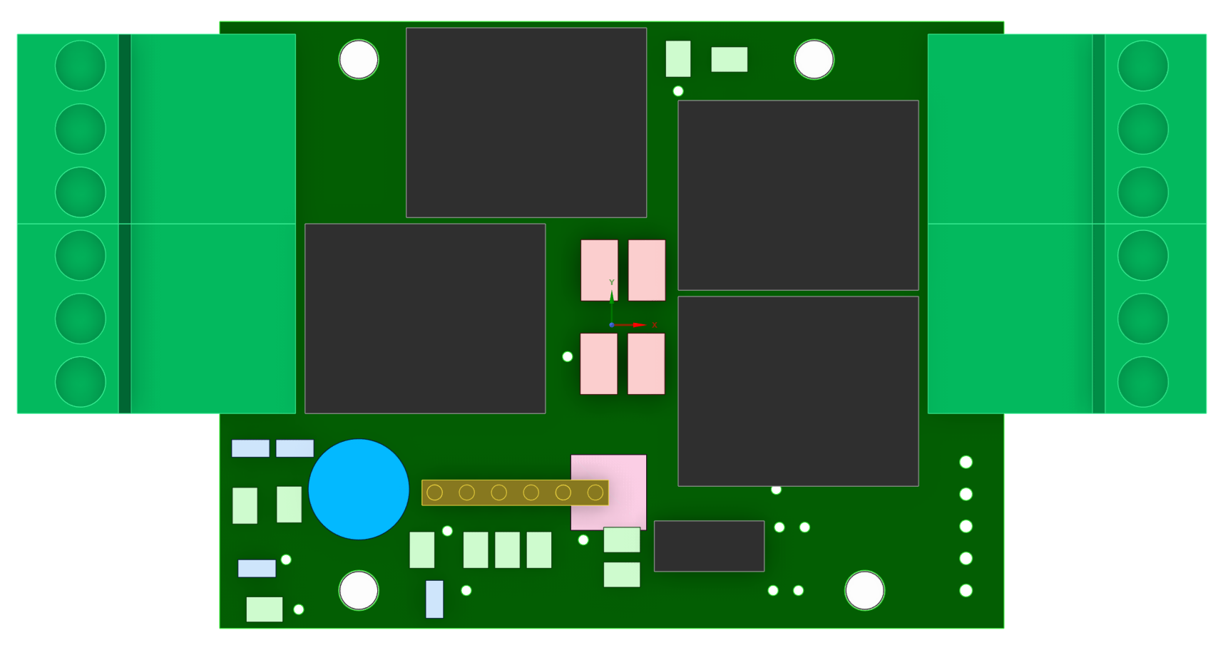
The RLY (relay) module is designed for safe, galvanically isolated power switching of electrical devices. It uses LEG-5 relays, rated for up to 15 A and 230 V. The module provides four independent channels. The MCU that communicates with the BIR module over the bus is powered from 3.3 V, while the relay coils are driven from 5 V.
Description of digital input modules will be placed here.
Description of analog input modules will be placed here.
...
Live demo description and access instructions will be placed here.
Demo DashboardContact information and project details will be placed here.